WHEN HEARING AIDS ARE
NOT ENOUGH 
On this page
|
| Back to Outline Go to next page |
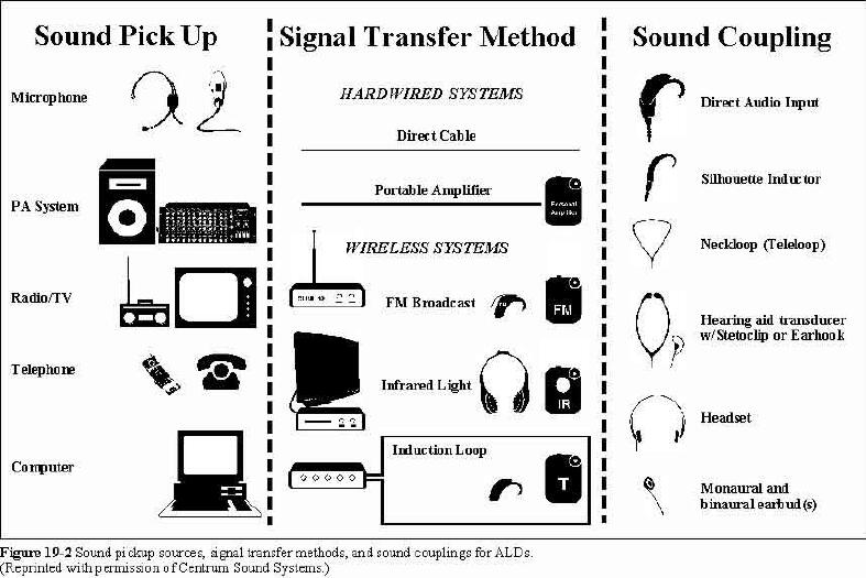
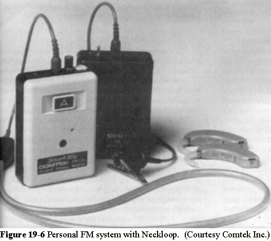
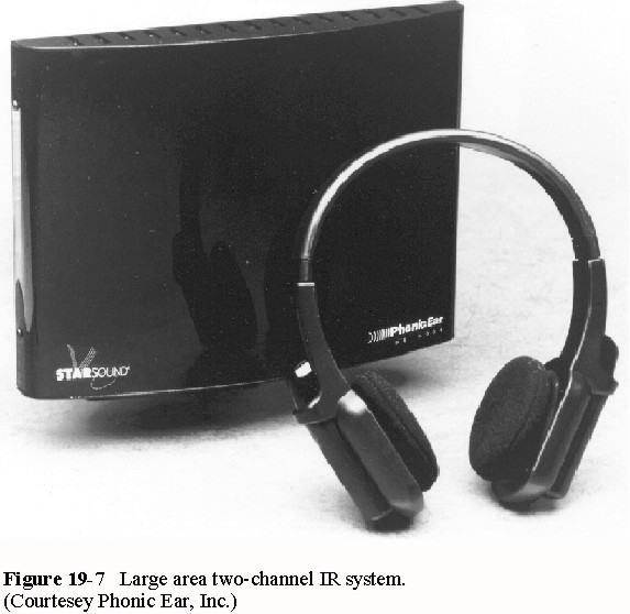
SIGNAL TRANSFER METHOD There are two principal methods of routing the signal from the source pickup to the sound generating transducer/coupler. It can be either hardwired or wireless transmission. Because most sound generating transducers are low impedance devices and require a stronger signal than that of the output of a microphone, an amplifier is required. Most amplifying devices have a volume control allowing the signal to be adjusted by or for the individual person's needs. Some device manufacturers also incorporate tone controls and balance controls to better accommodate the individual user's needs. Hardwired Systems As the name indicates, the hardwired devices make the connection between the sound source and the output by means of a wire or cable. The terms wire or cable are usually associated with commercial installations. But due to the relative small size of the cables associated with personal ALDs, these are referred to as cords. The cord connecting the source signal to the amplifier is shielded to avoid inductive interference caused by other electrical installations. The cord connecting the output transducer to the amplifier does not need to be shielded because of the low output impedance of an amplifier. In the past, facilities, particularly churches, provided assistive listening by means of hardwired headset connections. Therefore, people with hearing loss were limited to seating at designated seats, usually within the first five rows. Large bulky headphones were the most common listening option, thus, these systems were never popular among people with hearing loss. But the development of cost-effective wireless systems in recent years has eliminated the need for commercial fixed hardwired systems. However, a personal portable amplifier is an economical solution for person-to-person conversations in noisy environments. The basic system consists of a pocket sized amplifier, a microphone, and an appropriate sound generating output transducer (see Figure 19-2). The microphone is often designed as a plug-in unit which eliminates the need for the microphone cord. In noisy environments, the microphone/amplifier is held close to the speaker's mouth thereby improving the SNR substantially. The plug-in microphone can also be attached to a short cord or simply replaced with a wired lapel microphone. This provides the user the option to use it as a hand-held microphone or as a lapel microphone. Pearl... A person with hearing loss is having difficulty understanding in even close person-to-person conversations in situations where the background noise level is unusually high, i.e. at restaurants, parties, and conferences. The person has hearing aids with T-coils but no Direct Audio Input (DAI) (described later in this chapter). A personal amplifier with plug-in microphone and a neckloop is a sensible solution. For TV or radio listening, a microphone extension cord can be inserted allowing the microphone to be placed close to the loudspeaker. Most newer TVs, VCRs and other audio equipment also have "audio output" jacks. The patch cord may be connected directly to such an output jack, thereby eliminating the need for the microphone as the pickup source. In spite of the high portability of these devices, the user has limited mobility to move around once the system is in place. Wireless Technologies The optimal solution to provide full mobility to the ALD user is by routing the signal from the sound source to the user by means of wireless transmission. There are three basic wireless technologies available today which provide different methods of transmission: Teleloop (induction loop) technology, FM broadcast technology, and infrared light technology. No single technology is best for all applications. Each type has its own advantages and disadvantages. All three types of assistive listening systems can successfully be applied, as long as their individual limitations are observed. INDUCTION LOOP SYSTEMS (Teleloop) The induction loop technology is the oldest and perhaps the most popular (among people with hearing loss) of the three wireless technologies. It is based on electromagnetic or inductive transmission and has the unique advantage that the signal is received directly by the user's personal T-coil on the hearing aid without the need for an additional receiver as is required by all other wireless technologies. Induction loop receivers are available for people with hearing loss without hearing aids or without the T-coil feature. The most common loop receiver is a pocket sized belt-clip device with headset or earphone. However, loop receivers are also available in a wand-like style or as a standard canal instrument (no microphone or volume control). Typical applications for induction loop systems include home radio/TV listening, small to medium size auditoriums, houses of worship, senior centers, council chambers, automobiles, and an endless number of counter applications where a physical barrier separates service personnel and individual customers, or where environmental noise may be excessive. The Concept of the Induction Loop The transmission component of an induction loop (room loop) system consists of an amplifier and a discrete wire (the loop) that runs along the perimeter of a room or designated area. The audio signal from the sound source is routed to the input of the amplifier and the amplifier's output is connected to the room loop. When an audio signal is delivered to the input of the amplifier, an alternating current (AC) flows through the loop. This current generates an inductive field inside the loop which is being picked up by the T-coil in the hearing aid or by a special loop receiver as illustrated in Figure 19-2. Conceptually it works like a transformer, where the loop simply is the primary coil of a transformer, and the T-coil the secondary coil of the transformer. Electromagnetic Field Strength and Frequency Response of Room Loops In order to take advantage of using personal hearing aids as receivers with room loops, the magnetic field strength must be chosen so that it is high enough to produce an acceptable SNR, but not so high as to cause overloading of the hearing aid. The international standard (IEC Standard 118-4) recommended magnetic field strength for a loop system is 100 mA/m, or -20 dB (± 3 dB) re 1 A/m, created with a 1 kHz sinusoidal input signal of level equal to the longtime average of the speech signal applied to the input of the system. This value generates an acoustical output from the hearing aid equivalent to the output of the hearing aid with normal speech level input to the microphone. The maximum recommended field strength is 400mA/m, or -8 dB re 1A/m, derived on the basis that the difference of the peak short-time average level between a speech signal (approximately 125 ms) and the longtime average level is approximately 12 dB. The recommended frequency response of the magnetic field with an electrical input signal is 100 Hz to 5 kHz ± 3 dB of the value at 1 kHz. Although the standard does not specify a fixed value for SNR, installation of a loop system can generally not be recommended if an ambient electromagnetic interference greater than 10 mA/m, or -40 dB re 1 A/m, can be measured. Loop Amplifiers There are two types of amplifiers used for conventional room loop applications: constant current and constant voltage. Both can be very effective, but are not equally easy to install. Although it is not necessary for an installer to be able to calculate wire sizes and output currents required for specific applications, it is important to understand the difference between the two amplifier concepts. Also, it is important to understand that it is the amount of current flowing through the loop, not the power rating of the amplifier, that produces the strength of the inductive field. The constant current amplifier, also referred to as an impedance matching amplifier, is designed to keep the output current constant regardless of the load impedance. Figure 19-5 shows a constant current amplifier designed for commercial applications. Similar but smaller loop amplifiers are also available for radio/TV listening. Pearl... A person with hearing loss has been fitted with two power BTEs and is doing very well in person-to-person conversations but is having difficulty understanding when watching TV. Turning up the TV volume does not help. A personal radio/TV induction loop system is recommended The user needs only to switch the hearing aids to T-coil position to receive intelligible speech from the TV set. Once installed, the system is completely maintenance free. For loop applications the load impedance is the resistance in the loop wire. The output voltage will change by whatever amount is required for the current to remain constant. The advantage of this design is that the loop wire typically can be a single 14-18 AWG hookup wire which is easy to install and/or conceal. For a room size, for example 40 by 60 feet, the total loop length would typically be close to 250 ft. long. The resistance in the loop wire with a 16-AWG hookup wire would be 1.0 ohm. With 14-AWG wire and same length loop, the resistance or load impedance would be 0.5 ohm. The output current would be the same with either loop which eliminates the need for complex calculations as may be required by its counter part, the constant voltage amplifier. In the constant voltage amplifier, the output voltage will remain constant irrespective of the load impedance. This type of amplifier is used for practically any loudspeaker application, commercial or residential. These amplifiers are typically designed to drive loudspeakers with impedances between 4 and 16 ohms (8 ohms being standard). Therefore, when using this type of amplifier for loop applications, the resistance in the loop wire must be equivalent to or greater than the manufacturer's stated minimum impedance for loudspeakers. In order to "build up" the resistance with a wire size commensurate with the current required, the loop wire may have to encircle the room 3 to 5 times. In large rooms this causes an increase in inductive impedance resulting in loss of higher frequencies. The only way of correcting for this loss is by means of equalization. Some amplifiers are equipped with graphic equalizers that can compensate for such loss. Although manufacturers offering constant voltage amplifiers for loop applications may perform the necessary calculations and provide loop wire or multiconductor cables, these may be difficult to install and/or to conceal. However, in spite of the many drawbacks of the constant voltage amplifier, it still remains very popular for portable meeting room applications, simply because of low cost and general availability. Installation Limitations and Considerations Room loops for residential applications such as radio and TV listening do not require any special considerations. However, before recommending room loops for commercial applications, it is important to ensure that a uniform field strength throughout the designated listening area can be achieved. A field strength variation over the covered area of ± 3 dB would be a reasonable criterion. The best way to achieve this is to install the loop at floor level or approximately 8 feet above the floor. It is important to be sure that the loop wire can be routed along the perimeter at one of those levels. Installing the loop on a wall at normal listening height (four feet above the floor for an adult person sitting down), will result in an intensive field strength increase closer to the wall and should be avoided. It is equally important to provide manufacturers of loop systems information about room size and layout, building materials, i.e., steel reinforced concrete floor, wooden floor, crawl space, etc. to ensure selection of an adequate loop amplifier. The crawl space or basement, if any, immediately underneath the room, often offer the easiest and best place for loop wire installation. To verify systems performance, the magnetic field strength can be measured with a field strength meter. Pitfall... It is not necessary to initially install a room loop in order to determine if an acceptable SNR can be achieved. The ambient electromagnetic fields caused by inductive coupling of other electrical installations is the source of interference that is present at all times. It can be heard through a T-coil hearing aid or measured with a field strength meter. Although most room loops are designed to encircle the entire, or part of, a designated seating area, the inductive field is not limited to within the loop. There will always be a certain amount of "spillover" outside of the physical layout of the loop wire. The amount of spillover varies with loop size and building materials. The loop signal may be picked up as far away as one half the width of the loop, i.e., with a loop size 40 by 40 feet, the signal may be heard up to 20 feet outside the loop. Therefore, multiple room loop installations can not be recommended where signals may interfere with adjacent rooms/facilities. FM BROADCAST SYSTEMS The frequency modulated (FM) radio broadcast systems offer people with hearing loss the greatest versatility of any of the wireless technologies. In principle, FM systems designed for hearing assistance applications work just like commercial FM broadcast systems operating in the 88 to 108 MHz range. However, in the U.S., the FM hearing enhancement systems operate at Federal Communication Commission (FCC) designated frequency bands in the range from 72 to 76 MHz and from 216 to 217 MHz. Manufacturers of transmitters are required to have their designs FCC approved, but no license is required to operate such systems. The transmitting power is restricted by FCC to a maximum field strength of 8 mV/m at 30 m in the 72-76 MHz band and 100 mW effective radiated output power in the 216-217 MHz band. The 216-217 MHz band is intended for auditory assistance applications only. However, there are licensed users sharing the same band. An FM hearing enhancement system consists of a transmitter and one or more receivers. With current technology, transmitters and receivers can be designed for portable battery operated applications, permanent installation, or a combination of the two. Therefore, FM systems may be used in a broad scope of applications ranging from small personal systems for indoor/outdoor use, (Figure 19-6), to educational and commercial large area applications. Transmission range vary depending on the equipment and antenna used, but is typically up to 100 ft for personal systems and up to 1,000 ft. or more for commercial large area systems. FM Technology FM stands for frequency modulation. An FM transmitter is designed to oscillate at a given radio frequency (RF) called the carrier or center frequency. When an audio signal is applied to a circuit within the transmitter called a modulator, the carrier frequency will change up and down in frequency in tune with the audio signal. The amount of deviation from the center of the carrier frequency is an expression of the intensity or volume of the audio signal whereas the speed with which it changes it's frequency is an expression of the audio frequency applied. The FM receiver detects these deviations and converts (demodulate) the RF signal back to an audio frequency (AF) signal. Wide-band and Narrow-band Frequencies The frequency range from 72 to 76 MHz can be divided into10 wide-band channels or 40 usable narrow-band channels. In the past, most systems manufactured were wide-band systems, but with increased demand for more channels and interference free channels and for rejection of near-frequency signals newer designs are based on narrow-band technology. Channelization of this band was dropped in 1989, thus there are no standards for assignment of carrier frequencies and band-widths. However, most wide-band frequencies are spaced 200 kHz apart with an allowed maximum frequency deviation of ± 75 kHz. Narrow-band systems in the 72-76 MHz band are typically spaced only 50 kHz apart with a typical maximum allowed frequency deviation ± 10 kHz. The maximum allowed occupied bandwidth in the 216-217 MHz band is 50 kHz. Some manufacturers have chosen to divide the band into 20 channels spaced 50 kHz apart whereas others may have chosen 40 channels spaced 25 kHz apart. Pitfall... The terminologies "narrow-band" and "wide-band" are not expressions for audio performance, but terms describing RF band-width technology for a specific product line. The transmitted and received frequency responses with either one of the two bandwidth technologies are wider than the frequency bandwidth of a hearing aid anyway. Wide-band Systems In conventional wide-band systems, the selection of a carrier frequency is made by tuning a coil (oscillator) inside the transmitter to the desired frequency. The receiver is then tuned to the same frequency. The tuning coils are often made "field-tunable" so individual users can make necessary adjustments for the purpose of avoiding outside radio interference, or simply to listen in on another channel. However, the electronic components are often voltage and/or temperature sensitive causing the transmitter or receiver to "drift" in frequency. To compensate for this drift, receivers are usually equipped with an electronic frequency control circuit - automatic frequency control or AFC. Another method of stabilizing the carrier frequency is by crystal control. In these systems, both the transmitter and receiver incorporate a crystal which oscillates at a specific frequency practically unaffected by change in operating voltage or temperature. The transmitting/receiving frequencies of such systems can only be changed by replacing the crystals. In some systems the crystals are made as plug-in modules which can easily be exchanged by the user. Because channels for wide-band systems were standardized before the channelization was dropped in 1989, most wide-band systems use the same ten carrier frequencies irrespective of manufacture. Each of the ten frequencies or channels have been assigned a letter between A and H. Systems that are field-tunable are normally factory tuned to operate on a specific channel identified by a letter. Crystal controlled devices are usually labeled on the crystal plug-in module or on the front face of the unit of non-replaceable crystal controlled devices. There is generally full compatibility between different manufacturers devices using this letter coding. Narrow-band Systems The advantages of being able to offer 40 channels as opposed to only ten are obviously advantageous, particularly at educational institutions or in multiplex movie houses, etc. where more than ten systems may be operating simultaneously. But there are other advantages with the narrow-band systems. In order to utilize all 40 channels, the bandwidth of the receivers must be as narrow as not to pick up signals transmitted on adjacent channels. The bandwidth of "true" narrow-band receivers must therefore always be less than 50 kHz as opposed to 200 kHz for the wide-band receivers. In practical terms, this means that narrow-band systems are substantially less susceptible to radio interference than wide-band systems. Narrow-band and wide-band systems are not compatible with one an other. Also, there are narrow-band systems available which are not "true" narrow-band systems. The transmitters may use narrow-band technology, but the filters in the receivers are not steep enough to reject adjacent channels. Thus, such systems can at best utilize up to 20 of the 40 available channels. The demands in terms of frequency stability and selectivity are far greater than for wide-band systems. Because the maximum deviation may only be up to 10 kHz, and on some systems only up to 3- 4 kHz, the transmitting frequency must remain stable within a few hundred hertz. Subsequently these devices are always crystal controlled. Narrow-band systems are available with fixed crystals, interchangeable crystals and with channel selector switches. Channel selector systems are based on crystal controlled digital frequency synthesis technology, or so-called phase-lock loop. From a theoretical point of view there is no limit to how many channels can be squeezed into a band, but attempts to make band-widths less than 25 kHz may have a high price tag in terms of degraded SNR and/or substantially higher acquisition cost. Narrow-band systems use two-digit channel numbering or a color code system. But since manufacturer's selected carrier frequencies and band-widths may not be the same, there is not necessarily compatibility between two systems labeled with the same channel number. Transmitter Types FM transmitters are generally available in two basic configurations, commercial large area transmitters and portable battery operated transmitters for personal or educational use. Whether they are designed for wide-band or narrow-band operation does not alter the mechanical or electrical configuration in terms of how they may be used for a specific application. The large area transmitter is commonly referred to as a base station. The type of antenna used determines to a high degree the transmission range. Some manufacturers supply a "rubber-duck" type antenna with their base station. Others provide pull-out telescopic type antennas. The transmission range is also influenced by building materials, but typical range is about 300 feet with the rubber-duck antenna and up to 1,000 feet with the telescopic antenna. To cover arenas and sport stadium size facilities, manufacturers offer large area or roof-top antennas to increase the transmission range. A connector for remote location of the antenna is provided on most systems. Rack-mount kits for installation in standard 19" racks are also available. When installing a transmitter in a metal rack cabinet, it is always necessary to remote locate the antenna outside the cabinet. Base stations have at least two input connections: one microphone input used for stand alone operation and one line level input used for hook up to PA systems (public address or sound reinforcement systems). Some base stations may also have a separate input for speaker level. When the base station is used with a PA system, a line-level signal is fed from the sound system's mixer to the line-level input on the base station. This is always the best method, but at times, it may be required to hook up to the loudspeaker output of the system. This should be the last resort because the sound system's intensity to the general audience should have no impact on the signal to the people with hearing loss. Newer designs may have an automatic level control to insure that the input signal always will be optimal for that particular system. Older designs usually have user adjustable input controls and some kind of visual level control in form of a peak indicator or VU meter. Personal body worn transmitters are designed for use with electret microphones. The actual microphone can be any one of the electret microphones described in the microphone section earlier in this chapter. The microphone cord is used as the antenna, therefore, it is important that the cord be fully extended. A curled up microphone cord will result in substantially reduced transmission range. The microphone input can also be hooked up to other sound sources but may require an attenuated patch cord (see DAI later this chapter). Some manufacturers also offer a separate auxiliary input (AUX) for use with high-level output devices. If the microphone is removed while using the AUX input, a special antenna may have to be connected in order to maintain maximum transmission range. For most personal systems this is approximately 100 feet. FM Receiver Types Unlike the transmitters, FM receivers may have different physical and electrical designs based upon user preference and/or applications. There are several specialty receivers available of which one is the auditory trainer (ATE). This type of FM receiver incorporates all the necessary electronic circuitry to simulate a hearing aid and/or binaural hearing aids. The auditory trainer can therefore be fitted by an audiologist to an individual student in much the same fashion as the student's personal hearing aid. ATE equipment of future designs will all be narrow-band systems incorporating digital frequency synthesis for ease of channel selection. A smaller more personal version is the BTE FM hearing aid illustrated in Figure 2. In this design, the FM receiver and hearing aid are combined in a behind-the-ear case. Because of space limitations, the antenna is located outside the case. The antenna is made from of pliable material so it can be moved away from the case for better reception. Some FM hearing aids are narrow-band systems operating on frequencies in the 72-76 MHz band. Channel selection, if applicable, is made with interchangeable crystals. The user can choose to operate it in FM mode only, hearing aid only, or a combination of the two. Combined with a personal transmitter, it offers an ideal solution for many students of middle school age or older. Because of the inconspicuous design, adults may also prefer this system to the more conventional belt-clip style receiver. However, there are limitations in terms of hearing losses to which they can be fitted and to receiving distance. To overcome fitting related problems and to offer a more economical and cosmetic solution, some hearing aid manufacturers offer an FM receiver boot. The FM boot is a separate module which fits onto the hearing aid in the same fashion as a DAI boot (see the DAI section later in this chapter). Like the FM hearing aids, the FM boots are based on either narrow-band technology usually designed to operate in the 216-217 MHz band or wide-band technology operating in the 72-76 MHz band. The only method of channel selection is through boot exchange. Major drawbacks with this design is short receiving distance and that the FM boot is powered by the hearing aid's battery, hence, battery life if relatively short. A unique boot receiver is the so-called TMX TeleMagnetix boot attachment. This attachment is designed to receive a pulse-width modulated 40 kHz signal from a neckloop attached to a special FM receiver as part of the ATE. The system has several advantages over conventional FM boot systems and neckloop/T-coil systems such as: no inductive disturbances (hum), broad audio frequency range (10 kHz), signal-to-noise ratio as good as with DAI input, not sensitive to head position and movements, low current consumption, and long receiving distance. A belt-clip style receiver is the most common style for personal use, and the only style recommended for commercial use. Used with appropriate sound coupling methods, i.e., DAI cord, neckloop, hearing aid transducer or so-called button receiver, headset, etc. in combination with the user's personal hearing aid, practically all degrees of hearing loss can be helped. Belt-clip style receivers are available with all previously mentioned technologies such as wide-band and narrow-band, field-tunable or crystal controlled, digitally synthesized or crystal interchangeable, etc. Some FM receivers are offered with a built-in environmental microphone. This version gives the user the flexibility to use it as an FM receiver or as a personal amplifiers previously described under hardwired systems. They may be equipped with a dual volume control system or a balancing control permitting the user to mix the environmental microphone signal with the FM signal. This is an important feature particularly in lecture or classroom type settings where questions from the general audience otherwise may not be understood. The environmental microphone feature may not be important to hearing aid users whose hearing aids can combine DAI with the hearing aid's internal microphone. Other features offered by some manufacturers include fitter adjustable or user adjustable tone controls and/or stereo output with left/right balance control. Pearl... A student fitted with power BTE's is having difficulty understanding the teachers because of poor room acoustics. The student is provided with a personal FM system. Since both BTEs have T-coils, the FM receiver is equipped with a neckloop as the most inconspicuous solution. Both BTEs also have combination MT switches (microphone and T-coil simultaneously), thus, the FM receiver does not need to have an environmental microphone. The transmitter microphone is a standard omnidirectional lapel microphone, but the student is also provided with a conference microphone for use at round-table discussions. INFRARED LIGHT SYSTEMS (IR) Infrared light can be used for signal transmission in same fashion as with FM transmission. However, unlike FM transmission and induction loop technology, infrared light can not pass through walls. Therefore, infrared light transmission is ideal for facilities operating several systems simultaneously in different rooms in that all receivers can be identical with no need for frequency coordination. Typical applications where the advantages of the infrared technologies are best utilized, include performing arts and multiplex theaters, courtrooms, and numerous applications where confidentiality is important. It is also an economical solution for home TV listening for people with hearing loss who do not have T-coil hearing aids or no hearing aids at all. Like other wireless technologies used for ALD purposes, no licensing is required to operate an IR system. The disadvantage of IR systems is that the receivers are susceptible to sunlight interference. This may limit usage to shady areas, or for some systems to indoor applications only. Also, because of the relative high power consumption of transmitters, most systems require hookup to a main outlet which limits portability. Infrared Technology An infrared system consists of three basic components: a transmitter (base station), an emitter, and a receiver. The audio signal is conveyed onto a sub-carrier in the base station which in turn is converted into infrared light by the emitter. The receiver detects the IR signal and converts it back into the original audio signal. IR systems used for ALD purposes are wide-band type systems implying a frequency modulation of the sub-carrier of approximately ±40 kHz. Narrow-band systems generally do not provide an adequate frequency response for people with hearing loss and are typically used for simultaneous language translation and other communication purposes. Pitfall... Contrary to common belief that infrared system are compatible with one another, infrared systems may operate on different sub-carrier frequencies. Only systems operating with same sub-carrier frequency are compatible with one another. At present, there are four sub-carrier frequencies used by ALD manufacturers of IR systems: 95 kHz, 250 kHz, 2.3 MHz, and 2.8 MHz. Early infrared ALD systems primarily used the 95 kHz sub-carrier with 250 kHz as an option for stereo or language translation. Until the mid-nineties, the IR technology appeared to be interference free. FM systems are susceptible to outside radio interference and loops systems to inductive interference caused by electrical installations and in particular the magnetic ballasts used with flourescent lights. However, with the introduction of the electronic ballast for flourescent lights, severe interference problems started to occur with the 95 kHz systems. The electronic ballasts generate a 30 kHz square wave signal that is picked up by the IR receiver. The interference can be heard as a loud howling sound that renders the entire system useless. Therefore, manufacturers of 95 kHz systems also offer 250 kHz systems as standard or on conversion basis. But since the electronic ballasts are used in new construction as well as for retrofit of older facilities, manufacturers of two channel or stereo systems have switched to 2.3 and 2.8 MHz sub-carriers. Figure 19-7 shows a 2.3/2.8 MHz two-channel large area system with headset. As of this date there are no known sources of interference (other than direct sunlight) with systems operating of those frequencies. There is general compatibility between manufacturer's equipment using same sub-carrier and frequency modulation. Transmitters and Emitters The audio signal is routed to the IR base station in the same way as for FM and induction loop systems. Home TV systems are usually supplied with patch cord for direct hookup and/or with a TV microphone. Likewise, the commercial systems can hook up to PA systems or operate as stand alone systems when PA systems aren't required. The input connectors and input level controls are the same as for FM systems and part of the base station section. The emitter section may be combined with the base station or it may be a separate unit referred to as an emitter panel (also called a repeater). Whether separate or not, an emitter consists of an array of special light-emitting diodes (LED). The number of LEDs determines how large an area can be irradiated. Home TV systems typically only require five LEDs, whereas large area systems may require between 50 and 144 per channel, depending of desired coverage area. Coverage information provided by manufacturers for a specific product should be used only as a guideline. Some of the more powerful IR panels offered for ALD applications can cover areas of 12,000 square feet or more in an oblong shaped room. It is a common belief that infrared systems are line-of-sight only. This is not necessarily so. Although invisible to the eye, infrared light behaves similar to visible light. It is reflected off light-colored walls and ceilings and absorbed by dark surfaces. To avoid shadow effects or simply to increase coverage area, most emitter panels are designed with daisy-chain capability (in a daisy-chain, the signal is routed from one unit to the next in a continuous chain with only one unit actually connected to the source). Therefore, IR systems can consist of a single base station with several emitter panels. The emitter panels should be installed ten feet or higher and angled downward. The best method of avoiding shadow effects is to install a panel on each side and point them diagonally across the room. Two low-powered emitter panel (i.e., each 5,000 sq. ft. specified coverage), will usually provide far better coverage than one high-powered panel (i.e., specified at 10,000 sq. ft). There are two basic methods of transferring the signal from the base station to the IR panel(s). Each method has it's advantages and disadvantages. One method is to transfer the sub-carrier from the base station via standard coax cable with BNC type connectors to the emitter panel. With this method, any number of emitter panels can be daisy-chained to a base station. The disadvantage is that each emitter panel requires power from a main AC outlet. The other method is to send both audio signal and a low voltage DC to the emitter panels along a three-conductor cable. Such systems are simple to install but there are limitations in terms of how many emitter panels can be added. Most emitter panels are designed for wall mounting. Supplied with pivoting brackets, they are easy to install and can be aimed for best possible coverage. Although not portable in the same fashion as the FM belt-clip style transmitter, even large venue IR systems can be set up in a short time. When mounted on floor stands, they can quickly be brought into a room and connected to the sound system. Portable battery operated systems are also available. The sound pickup is through a built-in boundary microphone. The LEDs are positioned in the dome for 360 degree IR radiation. IR Receivers One of the reasons that IR systems have become very popular is the high quality sound reproduction through IR headsets. Available in two versions, over-the-head and under-the-chin style, they provide unsurpassed fidelity for people with mild to moderate hearing losses. Both types are available in mono and stereo versions. Pearl... A person is fitted with two canal instruments and is doing very well. However, when watching TV at home, the TV's volume control is set so loud that is a nuisance to other family members and neighbors. A personal infrared TV system with an under-the-chin style headset solves the problem. The more conventional lavalier-style receiver is used mostly for commercial applications. It can be fitted with any sound coupling method (see Figure 2) from direct audio input to neckloops as described later this chapter. Most over-the-head style receivers radiate an inductive field compatible with the T-coil sensitivity of hearing aids. Some of the under-the-chin style receivers are also available with output jacks for use with neckloops, silhouette inductors, and DAI to hearing aid(s). The critical elements for good reception is positioning of the optical lens capturing the IR signal in combination with the amount of power radiated. The over-the head style receivers provide 360 degree reception as the receiving lens (or lenses) is positioned so it can "see" the emitter panel from all directions. On lavalier-style and under-the-chin style receivers, the lens is located as to receive signals coming from the front. Wide angel lenses offered by some manufacturers may have receiving angels up to 160 degrees. Shadow effects from people moving in front of the listener may result in occasional poor SNR, or at times, for the receiver to completely drop out if equipped with a squelch. Squelch is a circuit that mutes the receiver function when no signal is present, or when the signal is too weak to provide an adequate SNR. Units without a squelch circuit would generate a loud unpleasant hissing sound when no IR signal is present. As mentioned earlier, the best method of avoiding shadow effects is to install two emitter panels and point them diagonally across the room. |
Go to next page |