WHEN HEARING AIDS ARE
NOT ENOUGH 
On this page
|
| Back to Outline |
BATTERIES AND CHARGING SYSTEMS Most older designs of personal amplifiers, FM transmitters/receivers and loop receivers operate on 9 volt disposable and/or rechargeable batteries. Operation time with this battery is relative short (less than 8 hrs. for some systems), especially with rechargeable Nicad batteries. Pitfall... It should be noted that there are two types of 9 volt Nicad batteries. The nicads offered by the ALD manufacturers are a 7-cell type (8.4 volts) whereas commercially over-the-counter types are only 6-cell (7.2 volts). The operation time between recharges may be severely reduced with the 7.2 volt battery. The majority of newer belt-clip designs, regardless of technology and application, operate on two AA size disposable and/or rechargeable batteries as the most economical power source. Disposable AA batteries are inexpensive and rechargeable Nicad batteries (1.2 volt cells) have sufficient capacity to last through the day in even the most current consuming systems. Irrespective of battery type, manufacturers offer two methods of charging the batteries without physically having to remove them. The output jack on receivers/amplifiers or Mic/AUX-INPUT jack on transmitters are often designed to also accommodate charging of battery. The charge cord is simply connected to the jack and the unit is left on charge overnight ready for use the next day. The charger can be a wall-type AC adaptor with a single charge cord for personal amplifiers, or, it may have a double cord for a transmitter/receiver combination. Multi-chargers accommodating between 10 and 20 units are also available. Other ALDs are designed with external contacts, so the unit may be "dropped" into the charger instead of connected to a cord. Drop-in chargers are usually available as two-unit chargers. Some chargers, especially for ATE, are designed to be expandable by adding additional two-unit modules, yet others, may be designed as multi-chargers accommodating between 10 and 20 units. There are also devices that are designed to accommodate both charging methods. Whatever the design, most devices are equipped with a charge indicator to insure the user that the unit is being charged and not just merely plugged in. As a general rule, all rechargeable systems using nicad batteries may be left on charge even if the units are not to be used for days. The expected life time of a nicad battery, claimed by manufacturers, may vary, but they all pretty much last between one and three years. There are devices that are not designed for use with rechargeable batteries. Most over-the-head style IR headsets operate on disposable AAA size batteries. Yet others may be designed with nonstandard rechargeable battery-packs or non-replaceable rechargeable batteries. SOUND COUPLINGS AND FITTING OPTIONS The sound generating transducer is usually the internal receiver in a hearing aid. The signal from the output of the amplifier or wireless receiver can be routed to the hearing aid's amplifier via a DAI connection if the hearing aid is equipped for this. An alternative routing method is via an inductive transducer to a T-coil in the hearing aid. Neckloops and silhouettes are the two types of inductive couplers used with ALD receivers. When the signal transfer method is a room loop, the hearing aid user only need to set the hearing aid's input selector to "T" position. If the hearing aid is not equipped with a DAI connector or a T-coil, or, if the person with hearing loss doesn't have hearing aids at all, the only alternative is to provide the user with an external hearing aid receivers/transducer, earbuds or headset that is driven directly by the ALD's receiver. Direct Audio Input (DAI) The usual input to hearing aids are acoustic through the microphone, or electro-magnetic through the induction pickup coil. However, there is a need, for example for educational purposes, for an electrical connection from sound sources, such as a radio, tape/CD player, infrared system or external microphone. The electrical audio signal is routed from the source directly to a socket on the hearing aid via a cord. The connection inside the hearing aid is usually made to the same point as that of the microphone. The above mentioned is referred to as DAI (Direct Audio Input). An alternative name, often used in Europe, is AUX (Auxiliary input). Physical and Electrical Standardization of DAI Efforts to use a common DAI plug and socket and compatible input/output signals were initiated by European dispensers and manufacturers in 1982. The consequence was a tacit understanding that a DAI system must consist of "Euro" compatible elements. The "Euro-audio-input System" was adopted by the International Electrotechnical Commission in Switzerland in 1984 as IEC standard 118-6. This standard calls for the behind-the-ear (BTE) plug of the DAI cord to be a 3-pin polarized plug of specific dimensions and signal polarity. The socket on the hearing aid must, obviously, be designed to accept the plug. Furthermore, the standard specifies that the input sensitivity required to produce a specific output shall be stated. This output is defined as being equal to the output generated with 70 dB SPL acoustic input to the microphone. It is typically in the order of 1 millivolt (mV). To day most hearing aid producing countries have adopted the IEC 118-6 Standard. The Direct Audio Input "Boot" The DAI plug is a physically large plug, and most hearing aids cannot accommodate its socket. Most hearing aid manufacturers, therefore, offer an adaptor - commonly called a boot. The boot is slipped onto the bottom of the hearing aid where it connects with the hearing aid's dedicated (small) DAI input contacts. The DAI plug is then inserted into the boot (Figure 19-8). Because the boot is dedicated to individual manufacturer's hearing aids - physically as well as electrically - it must be obtained from the manufacturer of the hearing aid with which DAI is to be used. Attenuation of Direct Audio Input Cords or Boots The signal level of most audio sources is too high to be connected to the hearing aid without a certain level of attenuation. The signal levels can be categorized as:
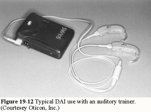
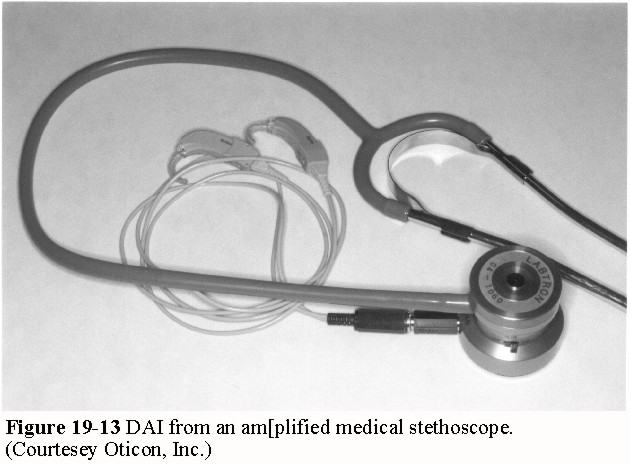
Pitfall... It is important to avoid using attenuated cords with attenuated boots. Such "double" attenuation will result in very weak output from the hearing aid. The end opposite the DAI plug must terminate with a plug that fits into the output connection of the audio source. Commonly used are 2-pin, 3-pin plugs and mini (3.5 mm) plugs. Direct Audio Input Sources and Connections The list of audio sources that can be used with DAI is virtually endless. Figure 19-9 shows an external microphone directly connected to a hearing aid via the DAI cord. As mentioned earlier, no attenuation should be used with external microphones as the sound source. Figure 19-10 shows the connection from a monitor-type TV. The jacks marked Audio Out (L and R) must be used for this type of TV. The volume control of the TV usually has no influence on the signal from these jacks, and 40-50 dB of attenuation is needed. It may be difficult to obtain a DAI cord that terminates with a phono (RCA) plug (monitor-type TVs use Phono Jacks). A DAI cord terminating with a mini (3.5 mm ) plug can be used with a mini-plug-to-phono-plug adaptor as shown in Figure 19-10. Figure 19-11 shows a coupler that fits in between the handset cord and the base of a telephone. The signal from the telephone is then picked up by a mini plug DAI cord that is inserted into the jack on the coupler. This set-up can give disturbance free binaural listening, which may not be possible if the T-coil of the hearing aid is used. Some 35 to 45 dB attenuation is needed in position High of the coupler and 15 to 25 dB is needed in position Low. The handset can be substituted by a hand-free headset if preferred. Auditory Training Equipment (ATE) is perhaps the most common use of DAI Figure 19-12. The signal is picked up from the earphone connection of the ATE receiver and routed to the hearing aids. The amount of attenuation ranges from between 20 and 50 dB, and depends largely on the position of the ATE receiver's volume control. Pitfall... The DAI cord doubles as an antenna for the ATE receiver. It should be kept long (at least 15") and not coiled up which would shorten the transmitting range of the ATE. Pearl...A student has been issued an FM system with a neckloop and has been very pleased with the performance. However, after starting a class where a computer is required, the inductive interference from the monitor renders the system useless. The student is issued a DAI boot and a cord for direct coupling to the receiver. When inserting the boot, the T-coil is automatically switched off so only the FM signal is picked up. Figure 19-13 shows DAI from an amplified medical stethoscope. The signal is routed from the output connection on the transducer part of the stethoscope and routed into the hearing aids. The volume control on the hearing aids, if any, should be left as for every day use. The signal level from the stethoscope is adjusted by the volume control on the transducer part until the loudness is satisfactory. The tubings to the ear (stethoscope part) are not used. Heart sounds are primarily composed of low frequencies. Hence, hearing aids with good low frequency reproduction will work best with this set-up. About 5-10 dB of attenuation is required. Other common DAI sources are infrared systems, walk-around stereos, tape players, CD players, computer sound cards, dictaphones, etc. Control Settings of the Hearing Aid The main switch of the hearing aid is normally kept in M (microphone) position during DAI use. That way, the environmental microphone remains active during delivery of the DAI signal. Additionally, most manufacturers offer a "DAI-only" option which disables the environmental microphone allowing only the DAI signal to be present. This can be achieved several different ways: One boot for DAI-only mode and another for DAI plus environmental microphone; a switch on the boot or hearing aid or a special design where the T-coil setting is used. In this design, when the boot is attached, an electronic switch disables the induction coil and allows the DAI signal to pass. The volume control, if any, is normally left in it's everyday position. In a classroom using ATE with DAI and the environmental microphone simultaneously, the attenuation may be adjusted to make the DAI signal (teachers voice) override 5-10 dB the signal from the environmental microphone. Inductive Transfer of Signals As an alternative to electrical input, inductive transfer may be used. This require that the hearing aid is equipped with a T-coil. The most typical use of inductive transfer is with a telephone. Surrounding the receiver end of the handset is a magnetic induction field which radiates the audio signal from the receiver. The induction field is picked up by the T-coil within the hearing aid. Not all T-coils are compatible with all telephones - stationary as well as mobile ones. In cases of poor compatibility, an induction amplifier (Figure 19-14) can be used. The one pictured has a small microphone facing the receiver of the telephone handset. The audio signal from the receiver is picked up by the microphone, amplified and converted into a strong induction field which is received by the hearing aid's induction coil. The strap-on amplifier shown has an electrical output connection allowing it to be used, e. g. with DAI to hearing aids. The connection may alternatively be used to drive two inductors, sometimes referred to as silhouettes (see Figure 19-14). The inductors are placed behind the ears together with either BTE or in-the-ear (ITE) type hearing aids. The inductors emit a strong inductive field which is picked up by the induction coil in the hearing aids. This is the only way to receive a binaural induction signal from a telephone. The strap-on amplifier can also be used as a "close-talk" microphone. In a noisy place it can be held close to a speakers mouth and the signal routed via DAI to the hearing aid(s). On a TV that has no electrical output connections it can be mounted on or close to the loudspeaker and used with an extension cord to the hearing aid(s), The same holds true for other audio sources that have no electrical connections. Some hearing aid users, in particular adults, prefer a neckloop as an alternative to silhouette inductors. This is because it fits around the neck and can easily be concealed. Also, binaural listening is possible without the need for attachments to the hearing aids if the user has two T-coil equipped hearing aids. However, due to the neckloop's very low impedance, an amplifier is required to provide a strong enough induction field for the hearing aid's T-coils. Induction (telephone) amplifiers such as the one shown in Figure 19-14 does not have sufficient power to drive a neckloop. Neckloops are most often used in connection with ALD and ATE receivers, but may also be hooked up directly to the headphone jack of TVs and walk-around type devices. Limitations and Drawbacks with Inductive Transfer Although no serious drawbacks or limitations exist with electrical DAI - other than limited mobility - some disadvantages and limitations may be experienced with inductive transfer. A humming sound is present in most environments. The hum may be perceived at an annoying level by people with milder hearing losses, but may be inaudible for people with more severe hearing losses. It is worse around equipment that radiate strong magnetic induction fields such as computers and monitors, fluorescent lights, microwave ovens and large electrical installations. Hearing aid manufacturers are often asked to shield the induction coil for hum. This is not feasible since such shield would render the T-coil useless. A good low frequency notch filter would relieve most of the hum, but such a filter requires several additional space consuming components in an analog hearing aid. An effective notch filter, however, is possible in a fully digital hearing aid without adding extra components. If a neckloop is used, positioning of the loop relative to the head is critical. Head positioning and movements can cause noticeable changes in output from the hearing aid. Telephones, induction loops and neck loops do not radiate their inductive field in the same direction. However, many hearing aid's induction coil can be physically positioned inside the hearing aid to optimize the inductive transfer, e.g., a horizontal position when worn works best with telephones and a vertical position is the only position that is compatible with room induction loops. Neither position is optimal with neckloops. Dual induction coils in both horizontal and vertical positions are often limited in effectiveness due to reduced sensitivity to avoid internal magnetic coupling (instability). Electromagnetic Compatibility (EMC) EMC is the most commonly used terminology when describing inductive compatibility and/or interference from, especially cellular telephones. Not all cellular phones produces sufficient inductive radiation to provide acceptable output from the hearing aid. Worse yet: most digital cellular phones transmit a signal that is picked up by the hearing aid as an annoying - often very loud - distorted buzzing sound. Worst interference can be expected from systems such as: TDMA (Time Division Multiple Access) and GSM (Global System Mobile). Less interference can be expected from CDMA (Code Division for Multiple Access). No hearing aids are immune for this type of interference which is caused by wires and component leads in the hearing aid acting as miniature antennas. Generally speaking, the smaller the hearing aid the less the interference. Fully digital hearing aids are most "immune" due to their few analog components and pathways. There are no easy solutions to the problem. Tiny capacitors mounted in the early signal path may be able to partially shorten the interference signal thereby rendering some alleviation. Metalizing the hearing aid casing is more effective, but may result in allergenic reactions. In addition to the hearing aid manufacturers, the telephone companies are searching for solutions as described by H. Stephen Berger (1997). Induction Coil Sensitivity Induction coils are tested according to ANSI S3.22 inside an electromagnetic field of 10 milliamperes per meter (10 mA/m) at 1,000 Hz. The hearing aid is positioned manually for best inductive transfer and the acoustic output SPL is recorded. ANSI S3.22 does not specify any requirement for sensitivity. In general, if the output SPL in a 10 mA/m field is equivalent to, or greater than, the output SPL obtained with 50 dB SPL acoustic input, the coil sensitivity is very acceptable. Controversial point... 10mA/m is for testing and comparing only. In real life, the hearing aid is normally subjected to at least 100 mA/m being 20 dB more than the 10 mA/m. External Hearing Aid Transducers, Headsets and Earbuds When the user's hearing aid(s) is not equipped with DAI and/or a T-coil, the only option is to use an appropriate sound generating transducer and, if necessary, remove one or both hearing aids. Obviously, this option also applies to people with hearing loss who do not wear hearing aids. When considering the number of hearing aid users and the number of hearing aids equipped with DAI and/or T-coils versus the total number people with hearing loss who can benefit from the use an ALD, the number of people falling into this category is rather large. Therefore, it is important to select a transducer type that can provide a high acoustic output in order to better utilize the residual hearing of the individual user. The external hearing aid receiver (transducer) commonly supplied by ALD manufacturers, offer several advantages over conventional headsets and earbuds. When fitted with a stetoclip for binaural or nylon hook for monaural listening as shown in Figure 19-15, the maximum output is close to 120 dB SPL. Some manufacturers offer the stetoclip with washable mushroom tips in place of the replaceable foam pads shown in the picture, thereby increasing the overall output to approximately 125 dB SPL. This type transducer can also be fitted with a standard size canal tip for individuals (monaural and binaural fittings possible), thereby increasing the output to more than 130 dB SPL. Conventional non-occluding headsets generally do not exceed 115 dB SPL whereas earbuds may be closer to 120 dB SPL. Only few manufacturers make technical specifications (ANSI S3.22) available for their products. Also, when headsets and earbuds are used with personal amplifiers or with ALD receivers equipped with environmental microphones, severe feedback problems may occur due to acoustic leakage. In addition, there are sanitary concerns with earbuds and headsets at public facilities, and some reluctance by users to use the over-the-head style headsets. Pearl... A city purchasing manager needs assistive listening systems for some of the city's public facilities which include the council chamber, the senior center, the community center, a small auditorium for employee training, and some courtrooms. Since no single technology is best for all applications, each facility is evaluated as a separate entity. A loop system with wand style loop receivers is recommended for the council chamber because of the low maintenance and administration factor. A loop system is also recommended for the senior center because several patrons have T-coil hearing aids. However, the loop receivers are the belt-clip style equipped with hearing aid transducers and stetoclips in order to provide the greatest possible dynamic range. Because of the large size and ever changing floorplan layout at the community center, an FM system is recommended. The transmitter is installed in the existing PA systems rack and the antenna remote located inside the auditorium. The receivers are supplied with hearing aid transducers and stetoclips. In addition, a supply of neckloops is provided (half the quantity of receivers). The employee training facility is also equipped with an FM system. However, the facility is not equipped with a PA system. Thus the transmitter is of the belt-clip style equipped with a omnidirectional lapel microphone. The courtrooms are equipped with infrared systems to insure full confidentiality. At the same time, receivers can be handed out from a central point regardless of which courtroom they will be used in. The chosen style is the over-the-head type because of their 360 degree reception capability. CONCLUSION When recommending an assistive listening device and/or system, one must understand the nature of the problem to which the solution has to be applied. The optimal solution for same type of problem will differ based on whether an ALD is for an individual person wishing to obtain a personal system, as opposed to a place of public accommodation. Many people with hearing loss share information about their hearing aids and/or assistive listening devices with each another. Likewise, facilities managers of public and/or commercial facilities also share information with one another. Just because one type of system works well for one individual or in one facility that doesn't mean it is the optimal solution for another. Thus, it is very important to recognize and explain the advantages and disadvantages of the individual ALD components as they relate to sound pick-up, signal transfer method, and sound couplings/fitting options for each application. The use of assistive listening devices has greatly improved the communication abilities of hearing aid users and nonuser as well. The availability and innovation of these devices will continue to improve and so will the public awareness and education. PREFERRED PRACTICE GUIDELINE Professionals Who Perform The Procedure(s) Audiologists Expected outcomes
REFERENCES American National Standard Institute. Specifications of hearing aid characteristics (ANSI S3.22 1987) New York: ANSI. Americans with Disabilities Act of 1990 (ADA, 1990) 42 USC 12101, Equal Opportunity for the Disabled. Washington, DC. Berger HS. (1997). Hearing Aid and Cellular phone Compatibility - working toward solutions. Paper presented at Gallaudet University, May 1997. Wireless Telephones and Hearing Aids: New Challenges for Audiology. Federal Communication Commission (FCC) 47 CFR part 0 to 19. Federal Register. Washington, DC. International Electrotechnical Commission. Characteristics of electrical input circuits for hearing aids (IEC 118-6 1984). Geneve, Switzerland: Bureau Central de la Commission Electrotechnique Internationale. International Electrotechnical Commission. Magnetic field strength in audio-frequency induction loop for hearing aid purposes (IEC 118-4 1981). Geneve, Switzerland: Bureau Central de la Commission Electrotechnique Internationale. Telecommunications Act of 1934 (ADA Amendment,1996). 47 USC 225, Telecommunications Services for Hearing-Impaired and Speech-Impaired Individuals. Washington, DC |